Sure 2416 - LED Dot Matrix Display Board
Interfacing to a Sure 2416 LED Dot Matrix Display Board
Browsing the internet, I came across a rather nice looking LED dot matrix board, and the price was incredibly low. The board in question is the Sure 2416, and is available from Ebay. I couldn’t resist buying one. All those flashing LEDs!
Once the board arrived, I looked around the internet for some information on it. There is lots of information out there, it’s just a matter of locating it. The obvious first place to look was the driver chip’s website (Holtek in this case), where I found interfacing code to the HT1632 device, and an application note written in the most obscure C dialect. This was a starting point, as it gave a general understanding of how to talk to the board.
With the Chinese application note, and the HT1632 datasheet at hand, I could now write Positron8 BASIC code in order to talk to the board.
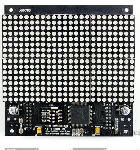
As the name suggests, the board consists of a matrix of 24 rows by 16 columns of Red LEDs, and is controlled by a dedicated chip, namely the Holtek HT1632. The datasheet for the 2416 board can be downloaded from here: Sure2416 Display Board.pdf, and the HT1632 chip’s datasheet can be downloaded from here: HT1632.pdf
The display board is shown below.
The board is interfaced via a 16-pin IDC connector, which is not a friendly connector for bread boarding, so I set about creating an adapter so I could use it on an Amicus companion shield.
The adapter was constructed from bits and pieces in my component drawers, namely a piece of Vero board (perf board), and 4 x 8-pin 0.1″ spaced SIL headers.
I cut a piece of Vero board, with 4 rows and 8 columns, and chiseled out (using a scalpel) the copper tracks in the middle, as shown below:
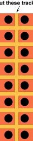
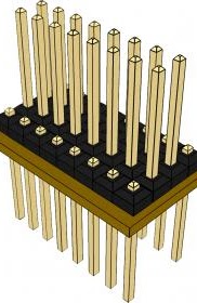
I then pressed the pins from two of the SIL headers flush with their encapsulate, and inserted them into the top of the Vero board. These will be the pins that enter the breadboard, so they will need to be spaced at 0.4″ intervals. The other two SIL headers where left as normal, and inserted between the flush headers, these will be the pins for the 16-way IDC plug. An illustration is shown below of the adapter. A Google sketchup model of the adapter can be downloaded from here:
Now I had the adapter, it was time to build the companion shield. The HT1632 chip uses a serial interface, and only requires 4 pins. Of course, we can’t forget the power and ground to the board, which is a standard 5 volts.
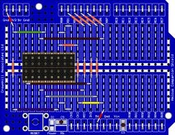
Shown below is an illustration of the layout used on the companion shield:
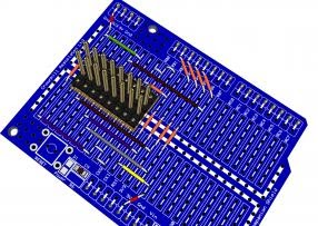
And a top down view of the same layout is shown below:
The interface is very simple, and consists of 4 connections (discarding the power):
PORTB.1 (RB1) connects to the WR pin of the display board (pin 5)
PORTB.2 (RB2) connects to the CS1 pin of the display board (pin 1)
PORTB.3 (RB3) connects to the Data pin of the display board (pin 7)
PORTB.4 (RB4) connects to the RD pin of the display board (pin 6)
+5 Volts connects to pins 12, 14, and 16 of the display board
0V (ground) connects to pins 8, 11, 13, and 15 of the display board
The WR and RD lines are both (active low) enable and clock lines, and each is waggled depending on what operation is required. For example, in order to write to the HT1632 device, bring the CS line low, the RD line high, and waggle the WR to clock out the value on the Data line.
In order to read from the HT1632, bring the CS line low, the WR line high, and waggle the RW line while reading the contents of ther Data line. Essentially that’s all there is too it, however, there are commands to use for each operation, but you need not concern yourself with them now, as the source code takes care of all that stuff for you, and has plenty of comments for the more inquisitive.
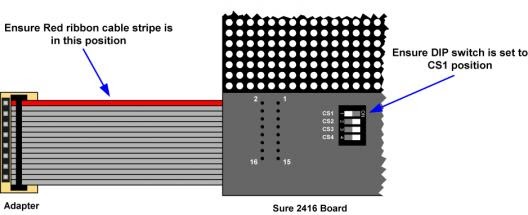
Connecting the display board to the companion shield is done by the use of a ribbon cable that was included with the board. For obvious reasons, it’s important to get the orientation of this correct or you may not have a working display board for very long. The illustration below should clarify the cable’s orientation. Just ensure that the red stripe of the ribbon cable is pointing up over (towards the Amicus18 USB and Power sockets).
One final check of the hardware, and we’re ready to use some code, which can be downloaded from here: Sure_2416_Display_Code.zip
Plug the USB cable into the Amicus18 board and companion shield combination, and load the Sure2416_Circle_Demo.bas file into the IDE:
'//
'// Circle demo for a Sure 2416 24*16 Dot Matrix Display Board
'//

  Include "Amicus18.inc"     	'// Configure the compiler for a PIC18F25K20 at 64MHz. i.e. An Amicus18 board
  Include "2416.inc"         	'// Load the Sure 2416 display interface routines into the program

  Dim bRadius As Byte           '// Holds the circle'//s radius

'//-------------------------------------------------------------------------------------

Main:
  Do                            '// Create an infinite loop
    For bRadius = 1 To 13       '// Create a loop for the size of the display
      tPixelColor = tPixelSet   '// Set the pixels
      HT_Circle(12,7,bRadius)   '// Draw a circle
      DelayMS 100               '// Wait a while so we can see what'//s happening
      tPixelColor = tPixelClear '// Clear the pixels
      HT_Circle(12,7,bRadius)   '// Erase the circle
    Next                        '// Until all circle sizes are drawn
  Loop                          '// Do it forever
Click on the “Compile and Program” button in the IDE, and as long as no errors are found, the program will be inserted into the microcontroller, and the display should burst into life. Click on the video to see what it should be doing (sorry about the poor quality video, but my camera isn’t good at close-ups):
For such a simple program, it gives a rather nice display! But that’s the power of the Positron8 BASIC compiler, all the interfacing (low-level) stuff is inside the “2416.inc” file, which we’ll discuss later.
There are several other demo’s included in the code download Sure_2416_Display_Code.zip, below is a video of each demo. Again, I apologise for the quality, or rather the lack of it!.
The 2416.inc file
This file contains the low-level interfacing subroutines for speed, but is very user friendly. The file is self contained, meaning that it will create the variables it requires, and initialise the display board when it is loaded into the program that s using it. All that you need to do is include the “2416.inc” file at the top of the main program.
HT_SendCommand(pCommand)
Send a command to the HT1632 chipset.
pCommand, as its name suggests, holds the command to send.
A list of commands is located at the top of the “2416.inc” file
HT_SendData(pAddress, pData)
Send a piece of data to the HT1632 chipset.
pAddress holds the address where pData is stored
HT_Plot(pXpos, pYpos)
Set, clear or Xor a pixel at pXpos and pYpos.
The pixel’s condition is dictated by the variable tPixelColor.
This can contain:
0 = Clear the pixel
1 = Set the pixel
2 = Xor the pixel with the contents of the pixel at its location
For example, to set a pixel at location 0,0 (top left) use:
tPixelColor = 1
HT_Plot(0,0)
To clear a pixel at location 0,0 (top left) use:
tPixelColor = 0
HT_Plot(0,0)
The above values have been given alias names:
0 (clear pixel) is named tPixelClear
1 (set pixel) is named tPixelSet
2 (xor pixel) is named tPixelXor
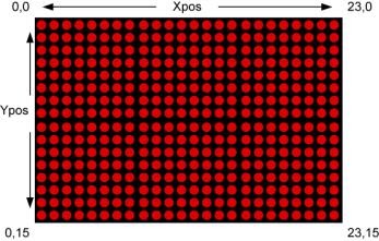
The LED’s display orientation starts at top left, as in a graphic LCD. Where the first pixel top and left is designated as 0,0. See below:
HT_Pixel(pXpos, pYpos, pReturn)
Return the state of a pixel (0 or 1) from pXpos and pYpos.
Unlike a standard function of the compiler, the returned value is located at the end of the list of parameters, in pReturn. For example:
Dim bPixelState as Byte
HT_Pixel(0, 0, bPixelState) ‘ Read the state of the pixel into bPixelState
HT_Line(pXStartPos, pYStartPos, pXEndPos, pYEndPos)
The above will draw a line from starting position pXStartPos, pYStartPos to pXEndPos, pYEndPos with whatever colour is held in the variable tPixelColor.
For example, to draw a line across the display from top left to bottom right use:
HT_Line(0, 0, 23, 15)
HT_Circle(pXpos, pYpos, pRadius)
Draw a circle starting at position pXpos and pYpos with a radius (in pixels) of pRadius, with whatever colour is held in the variable tPixelColor.
For example, to draw a circle in the middle of the display with a radius of 5 pixels use:
HT_Circle(12, 7, 5)
HT_DisplayChar(pXpos, pYpos, pChar)
The above will display an ASCII character held in pChar, starting at position pXpos and pYpos. Note that the X and Y positions are in pixels, and the starting position of the character is top left.
For example, to display the letter “A” at pixel location 0,0 use:
HT_DisplayChar(0, 0, “A”)
or
Dim bChar as Byte
bChar = 65
HT_DisplayChar(0, 0, bChar)
Notice that there is a single pixel gap above the character, this is so that when two characters are placed above one another, they do not merge.
HT_DisplayString(pXpos, pYpos, pString)
Display an ASCII string held in pString, starting at position pXpos and pYpos. Note that the X and Y positions are in pixels, and the starting position of the character is top left.
For example, to display the characters “HELLO” at pixel location 0,0 use:
Dim sMyString as String * 5
sMyString = “HELLO”
HT_DisplayString(0, 0, sMyString)
HT_Clear()
Will Clear the LED display.
Above all, have fun. I know I did writing the code for this excellent little board. And I look forward to reading your own creations using the “2416.inc” file. Now whose up for a game of space invaders, tetris, or pong?
Les Johnson